Understanding virtual routing forwarders
As network engineers, we have a deep understanding of network segmentation with virtual routing forwarders, VRF. In our data centers, we are using L3 VRF as we are using distributed routing in the data center and trying to apply segmentation on the network level. During design discussions with other teams in our company teams I see that they do not have a clear understanding of network virtualization even when they are using it:) I will also give some basic information about how we do L3 VRF leaking using route targets.
I will not give details about MPLS, BGP, VXLAN instead I will try to explain L3 VRF.
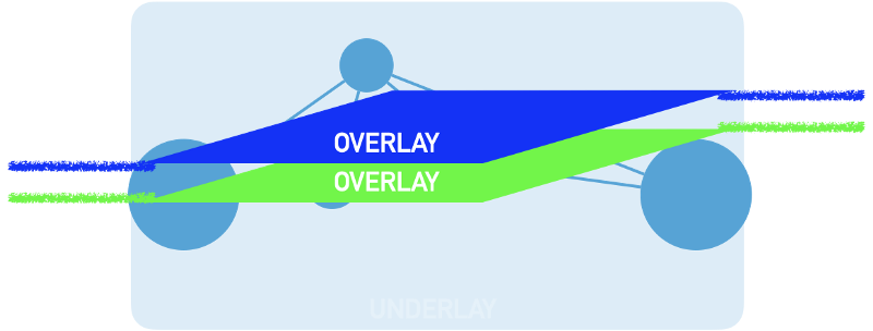
Network Virtualization
Network virtualization is commonly known as creating multiple virtual networks, overlays, over a common network which is called underlay.
Underlay is the common network consisting of multiple devices that generally uses dynamic routing protocol.
I will not focus on how to create an underlay network. Besides static routing options which are hop by hop, dynamic routing protocols are used to create underlay networks.
Generally, underlay networks do not have to be controlled by the same organization. As long as there is reachability between any node, it’s can be an underlay. Sometimes I prefer to use the term backbone instead of underlay.
As a network consists of multiple physical devices we need to understand how we virtualize a single network device and connect these virtual networks on those devices.
From a networking perspective, it does not matter if it’s a Linux machine or a router e.t.c. The main purpose of a network device is to connect two or more networks and forward packets between them. They need two basic functions;
- A forwarding information table, FIB: They need to know where or which connected device to forward the packet. MAC table e.t.c.
- A routing information table, RIB: Some mechanism that will build the forwarding table from varying resources. IP route table e.t.c.
To virtualize the network we have to virtualize those two basic functions.
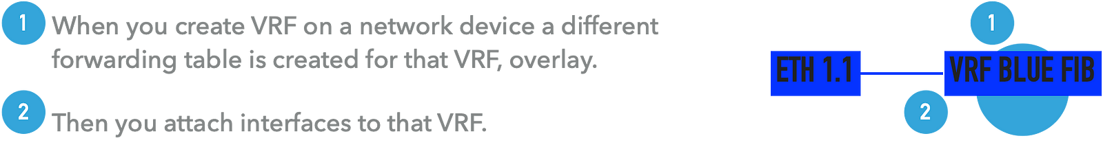
Virtual routing forwarders, VRF, creates these two basic functions on the device level.
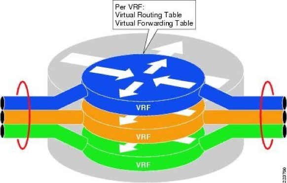
From that perspective, a VRF is like Linux Namespaces, they create different routing forwarding tables on the devices and isolate the networks on that device from the forwarding perspective.

But there is more than that when we want to create those virtual networks on multiple devices and connect them. The problem turns into connecting those virtual forwarding paths on separate devices.
Connecting actual data paths between those VRF’es or namespaces can be done in various ways. Tunnels can be used where tunnel endpoints lie in the appropriate namespaces. More advanced technologies like MPLS, Segment routing, or even SDN-based controllers can be used. Let’s focus on connecting virtual routing tables. But this is another story, I will like to concentrate on the basic VRF leaking method.
BGP is used for connecting those virtual forwarding tables (routing tables of the namespace). Tag or tags are associated with each virtual routing table and sent to other underlay devices.
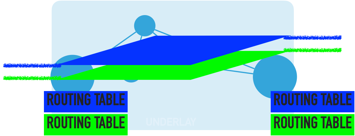
By sharing the local virtual routing tables all nodes have common information about the overlays virtual routing tables on each of the underlay devices.
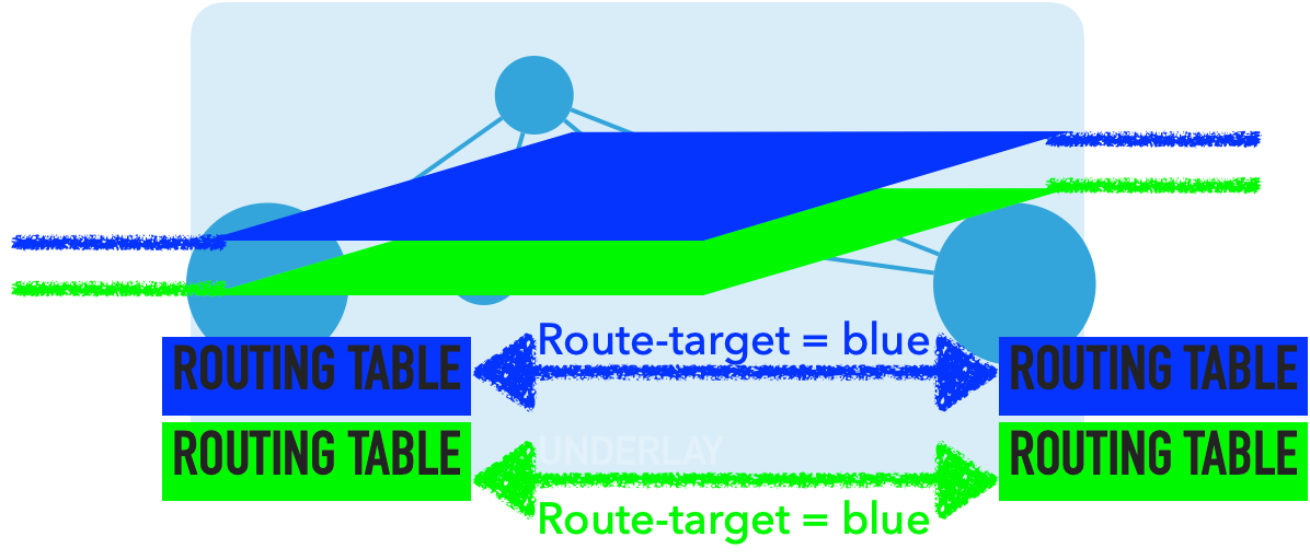
For tagging the routes in virtual forwarding tables Route-targets are used for that purpose while using BGP-based solutions like VPN4, EVPN e.t.c.
Simply, very simply BGP is used to distribute overlay network prefixes between backbone devices. BGP adds a tag or tags mentioned above, representing the overlay network.
Route targets are those tags that are attached to the overlay network while distributing over the underlay between each backbone device.
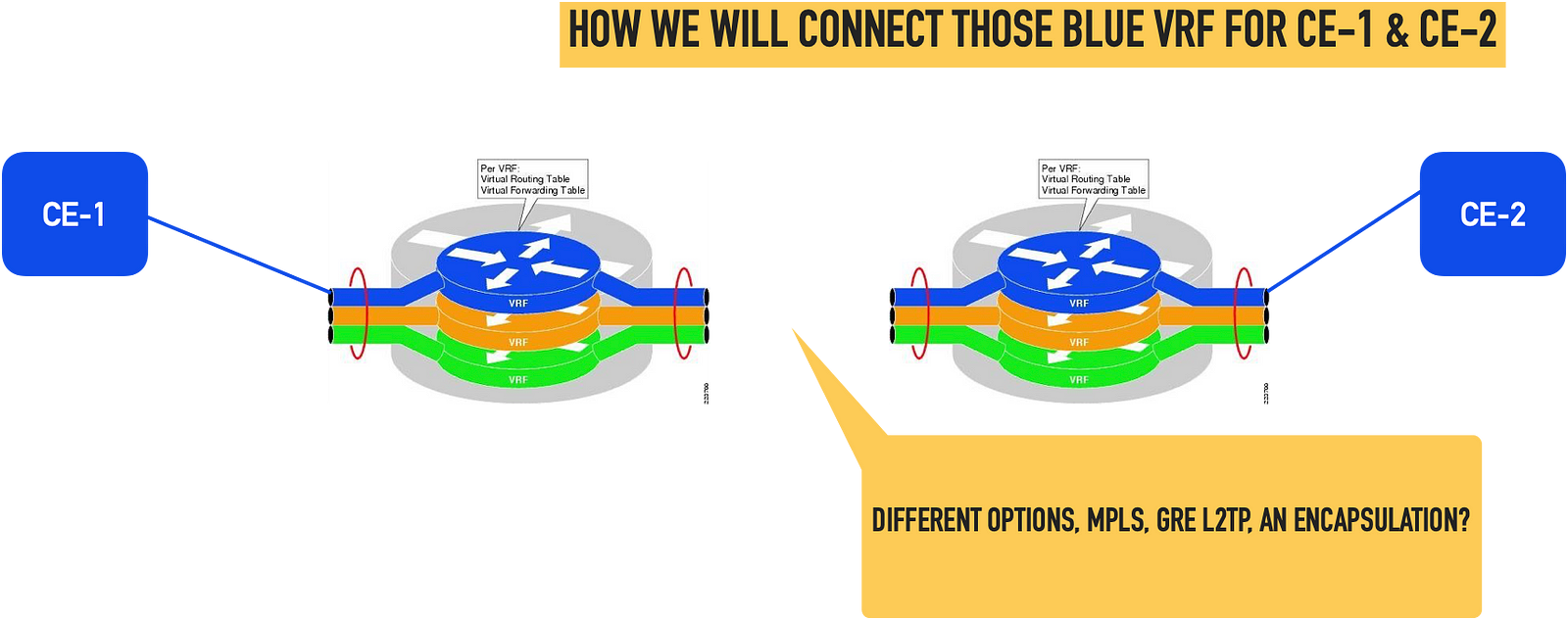
Let’s look at basic steps and understand how we are connecting two different edge devices through the overlay network.
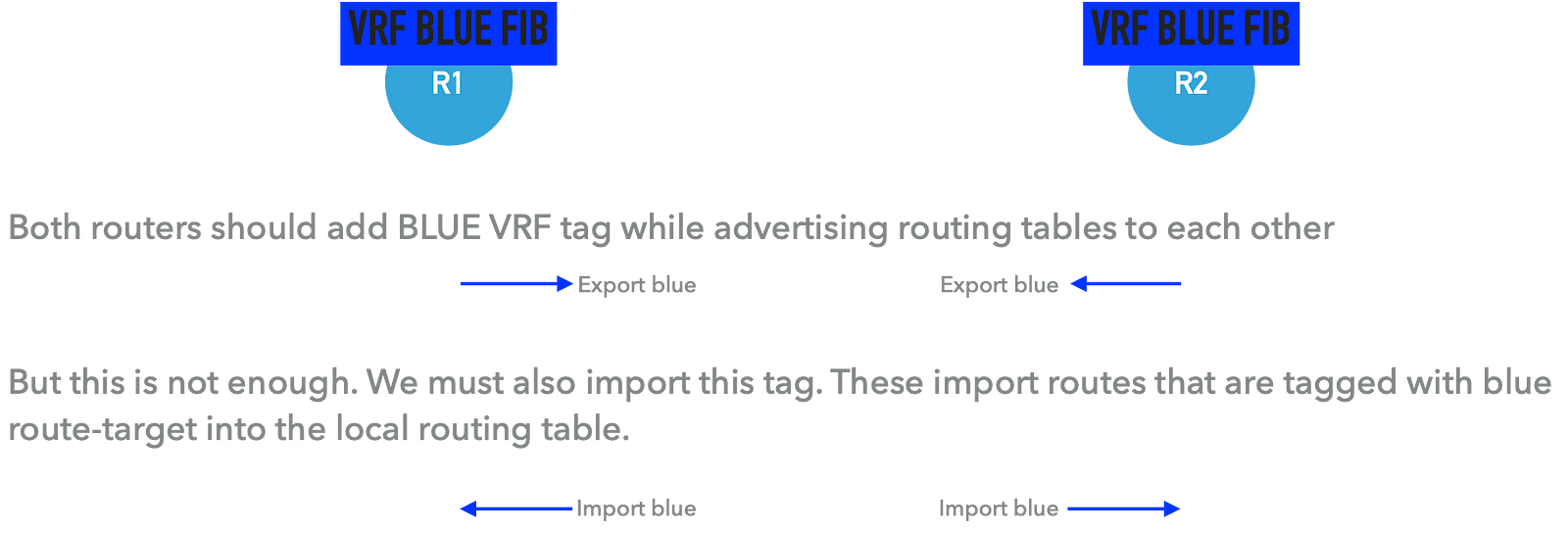
As we explained, if you want to connect those two VRF on different network devices you add route targets to your local routes with route targets using BGP.
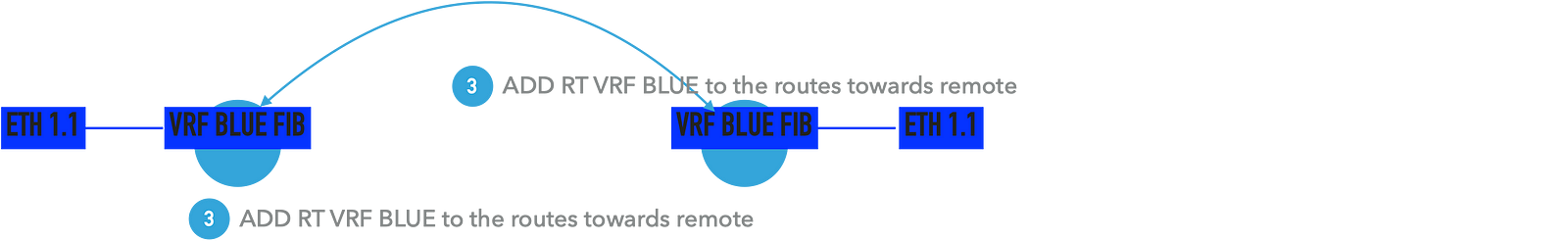
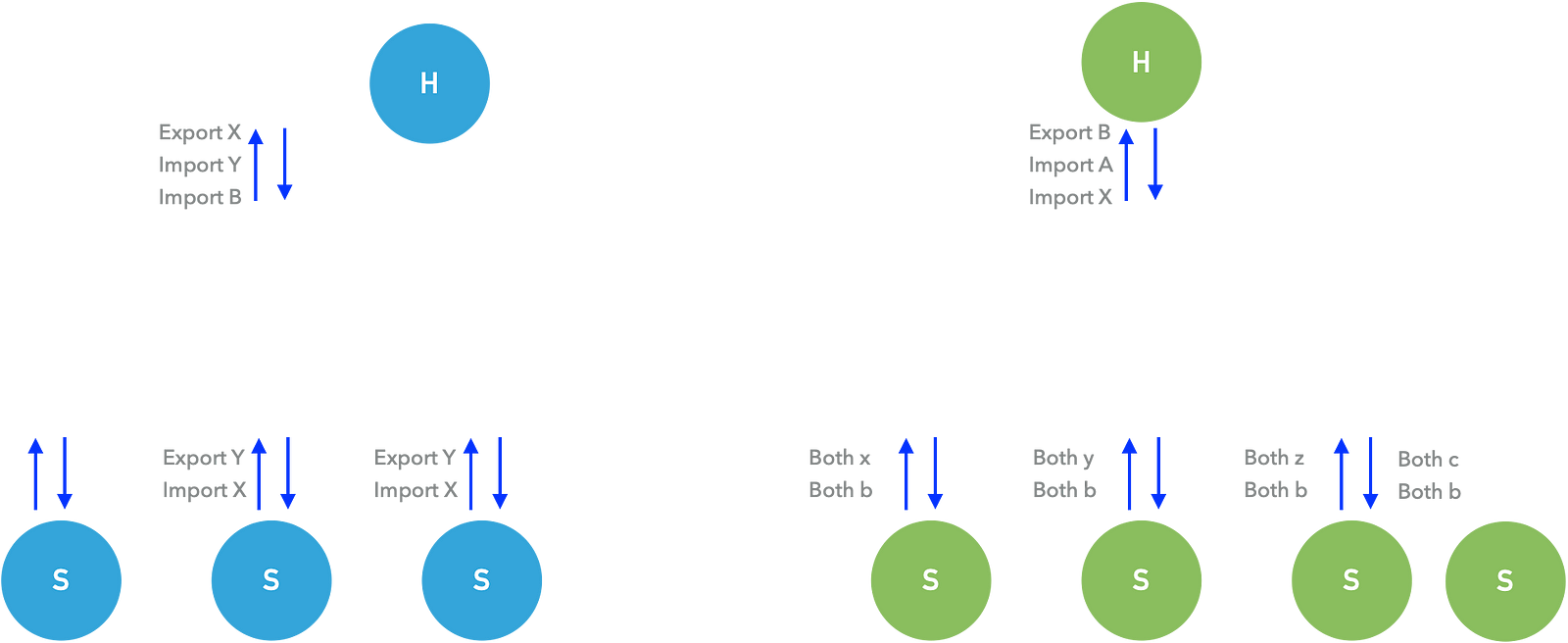
Here comes the usage of import and export definitions ( mostly vendor-wide).
Export: adding route-target value to the local routes. This value can also be used while advertising those routes via BGP or any other routing protocols.
Import: Means import a route target into the local routing table.
With considering the above example
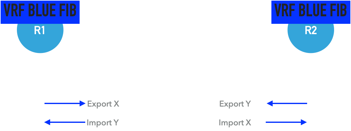
We may use different route-target values while importing and exporting.
For example, R1 and R2 will use different route-targets while exporting their blue vrf routes. Thus we need to import a remote route-target.
A more advanced example can be creating Hub and Spoke networks.
We have a firewall service, and two different overlay networks, two different customer networks which should access the internet via firewall but should not access each other.
This is a similar setup with a central headquarters which is connected to the remote offices. But remote offices do not have direct access to each other.
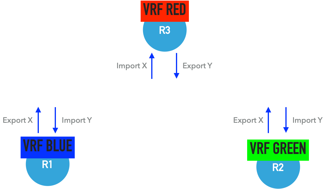
I need to comment for this example that this solution more likely depends on the network device. VRF RED contains VRF BLUE and VRF GREEN networks. If the network device MUST NOT have the capability of local route lookup for a VRF (local vrf table lookup, VRF based MPLS label, or VNI switching) this can not be achieved. From L3 MPLS VPN terminology it must use per-ce, per-prefix label switching.
More advanced usage of route targets different hubs for different overlays.